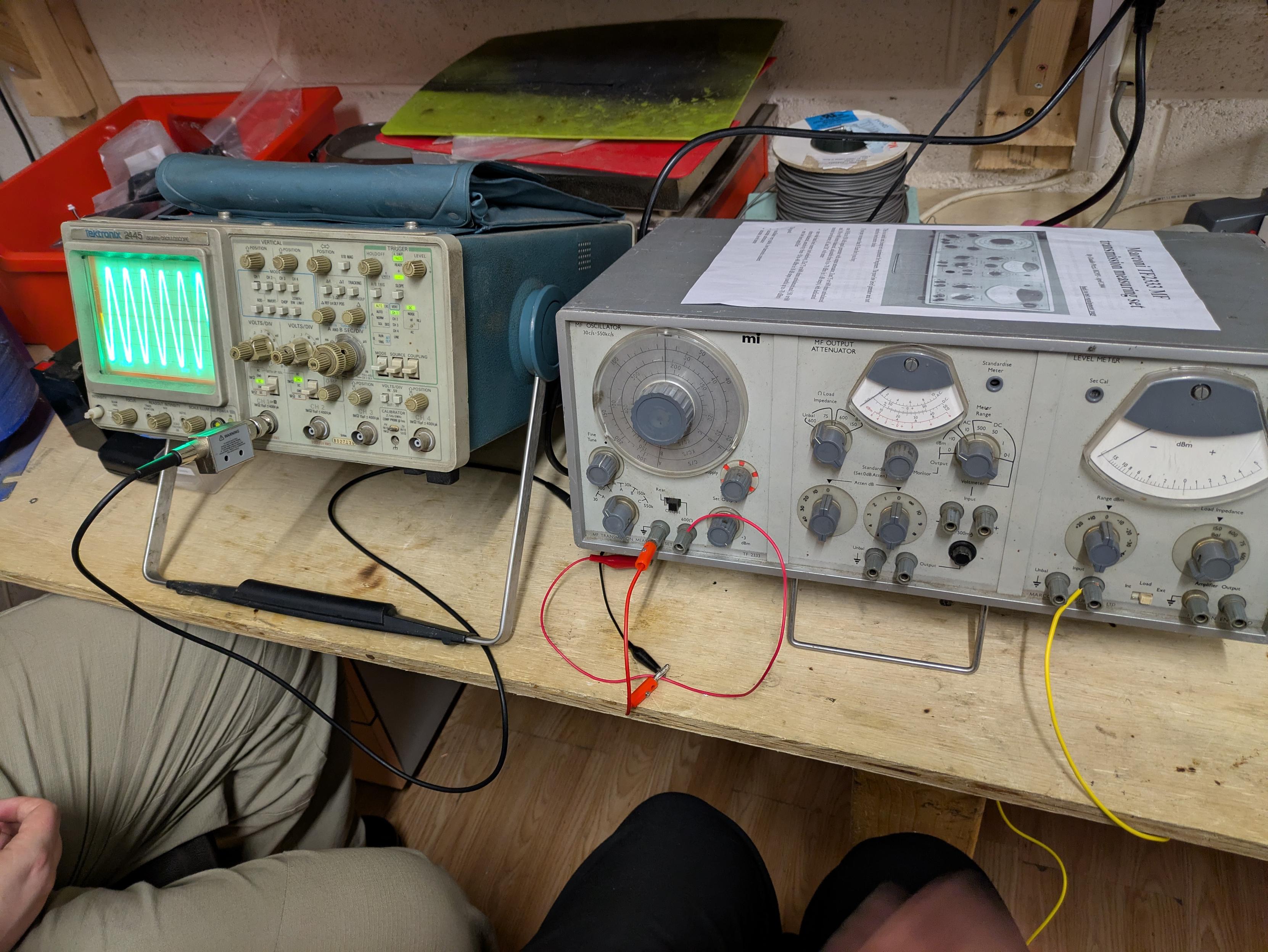
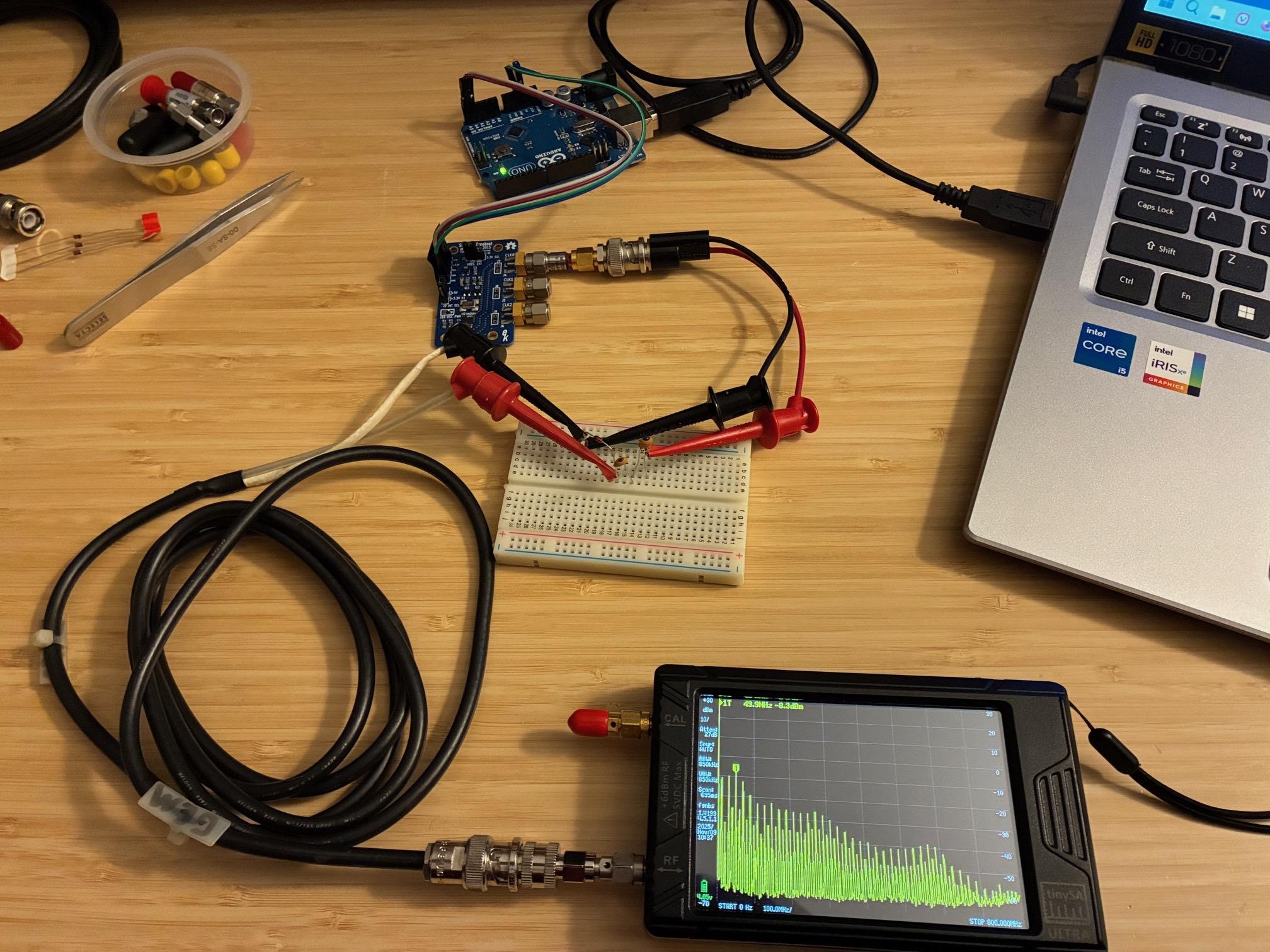
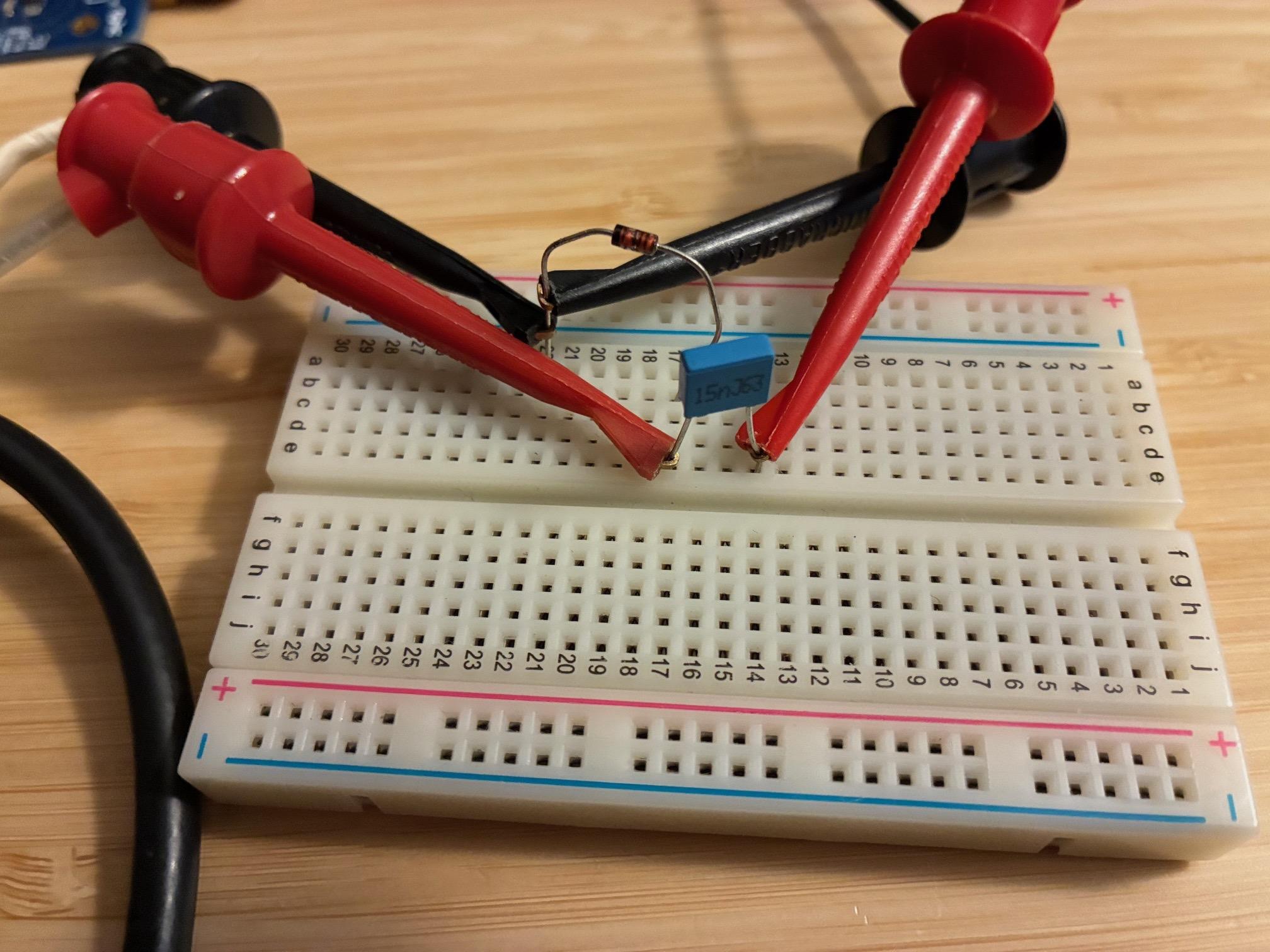
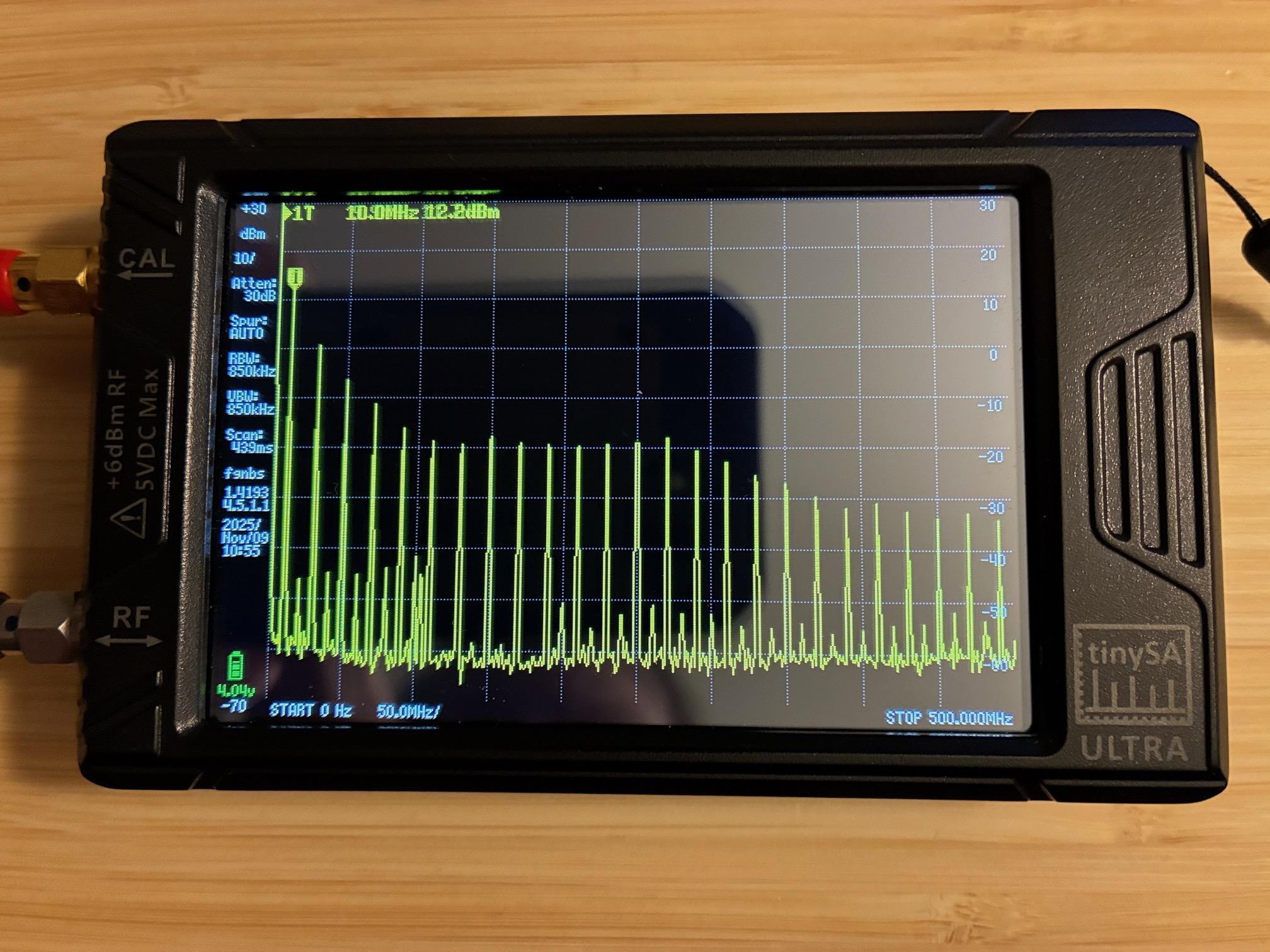
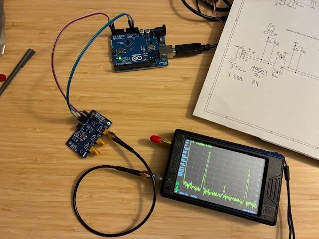
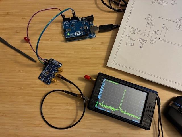
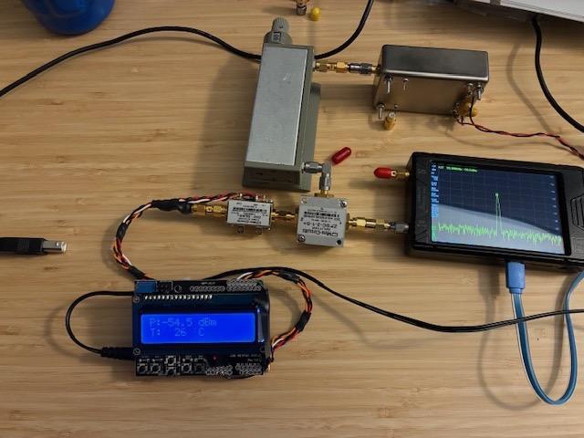
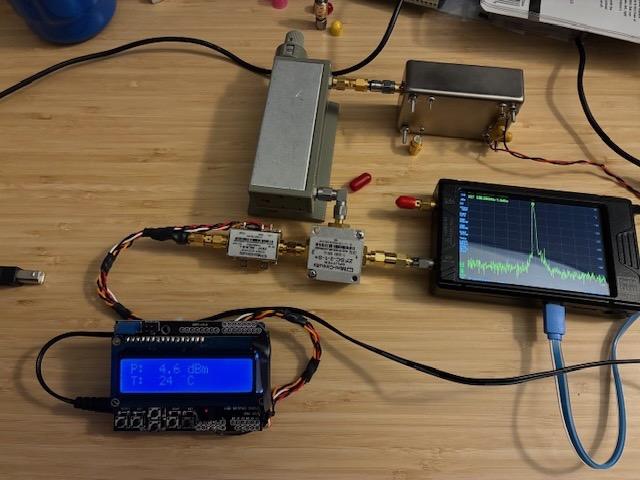
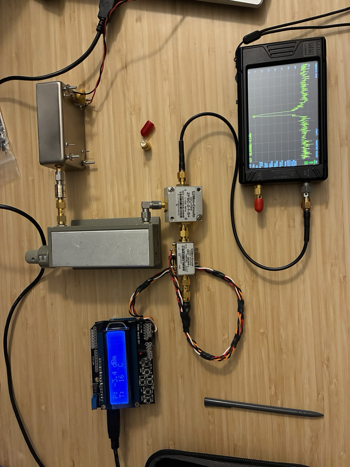
Discussion
Loading...

#Tag

  • About
  • Code of conduct
  • Privacy
  • Users
  • Instances
  • About Bonfire
Gary @N8DMT
@n8dmt@mastodon.radio  ·  activity timestamp last week

Exploring lower cost alternatives in measuring RF filter frequency response… Added a RTL-SDR to my SATSAGEN controlled scalar network analyzer setup just to see if how well it might work. TLDR: It works pretty well! Isolation between TX/RX is improved with this setup. Details in the blog post at: https://qsl.net/n8dmt/pluto-rtl-sdr-and-satsagen/index.html
#HamRadio #TestEquipment #RTLSDR

N8DMT

Pluto + RTL-SDR & SATSAGEN

Have been using ADALM Pluto SDR with Alberto IU1KVL's SATSAGEN software and wondered if there was benefit to using an…
Screen capture of SATSAGEN running on the Ham Win11 PC, with the software controlling the RTL-SDR receiver and Pluto SDR transmit source. A frequency sweep is running from 70 to 1200 MHz. The plot shows the reference line at 0 dB and the classic low-pass filter shape below that the Mini-Circuits SLP-300 filter provides (attenuating frequencies above the pass band up to 300 MHz).
Photo of a RTL-SDR receiver stick testing a Mini-Circuits low pass RF filter with a Pluto SDR as a transmit source.
  • Copy link
  • Flag this post
  • Block
Gary @N8DMT
@n8dmt@mastodon.radio  ·  activity timestamp 3 weeks ago

Si5351 CLK1 Output: Adding two low pass and one high pass filters cleans this right up. Spurious are now > 50 dBc!
#HamRadio #TestEquipment #Si5351

Photo of test setup with three blue SMA filters added to the CLK1 output to remove harmonics and sub-signal junk. All spurious are now more than 50 dBc.
  • Copy link
  • Flag this post
  • Block
Gary @N8DMT
@n8dmt@mastodon.radio  ·  activity timestamp 3 weeks ago

EtherKit Si5351A (Rev C) Mystery Solved: Root cause for the board’s +3.3VDC rail short to ground was the presence of J10 installed on the CCA. This shorts out the supply due to the use of the ECS-250-8-30B crystal which has GND connections on non-crystal corners. With jumper cut, the board works! Now to figure out a best use for this multi-output programmable square-wave test oscillator. Maybe write a LabVIEW front-end controller to maximize versatility?
#HamRadio #TestEquipment #FiltersNeeded

Quick photo showing EtherKit Si5351 supplying 175 MHz on CLK1 output. Simple example program used for this test.
Quick photo showing EtherKit Si5351A board supplying 14 MHz output on CLK0 output.
Screen capture of Rev C schematic showing J10 (Osc Power) connecting X1 Pin 4 to +3.3VDC board power. J10 must be removed to use a ECS crystal on board and installed if a crystal oscillator is used instead. My board has a crystal and had J10 factory installed. This shorted out the +3.3VDC regulator. (Am sure it was not happy, but did not SMOKE.)
Screen capture of the ECS-250-8-30B package showing non-crystal package corners are connected to package ground.
  • Copy link
  • Flag this post
  • Block
Gary @N8DMT
@n8dmt@mastodon.radio  ·  activity timestamp last month

DIY RF Power Meter Achievement Unlocked (initial functionality achieved). Reviewed code, made tweaks, found cal-offset magic numbers and calibrated temperature (single point) and input RF level over -55 to +5 dBm at my test oscillator’s frequency of 100 MHz. RF Power Meter works stand-alone (no PC). Would like to add serial output data in future, but no rush at the moment. Thanks to DL9SEC for sharing his Arduino code for a similar RF sensor!
#HamRadio#TestEquipment#RFPower

Photo of the +5 dBm level test using same setup as -55 dBm, just different step attenuator setting. Sensor is within 1 dB of TinySA-Ultra reading over +5 to -55 dBm level (measured in 10 dB steps). Also calibrated temp reading using a separate 1-wire/Arduino sensor to be within 0.5 C at the set point temp.
Photo of -55 dBm calibration setup with 100 MHz oscillator, 5 dB pad, 0-70 dB 10 dB step attenuator, 2-way splitter, TinySA-Ultra level monitor, and Mini-Circuits ZX47-55 sensor connected to an Arduino with LCD display shield. Sensor is powered from a +12V wall wart power adapter. It works!
  • Copy link
  • Flag this post
  • Block
Gary @N8DMT
@n8dmt@mastodon.radio  ·  activity timestamp last month

DIY RF Power Meter is “almost working” with reasonable temperature (C) and “close at about 3.5 dB low” power measurement for values > -20 dBm. RF level under range kicking in at -33 instead of -55 dBm. More debug work (and fun) ahead. #HamRadio#TestEquipment#NotLabVIEW

Test setup for RF power meter with +13 dBm 100 MHz oscillator, 10 dB pad, 0-70 dB 10 dB step attenuator, 3.3 dB splitter to sensor and TinySA-Ultra spectrum analyzer.
  • Copy link
  • Flag this post
  • Block
Log in

bonfire.cafe

A space for Bonfire maintainers and contributors to communicate

bonfire.cafe: About · Code of conduct · Privacy · Users · Instances
Bonfire social · 1.0.0-rc.3.13 no JS en
Automatic federation enabled
  • Explore
  • About
  • Members
  • Code of Conduct
Home
Login