Discussion
Loading...

Post

  • About
  • Code of conduct
  • Privacy
  • Users
  • Instances
  • About Bonfire
Gary @N8DMT
@n8dmt@mastodon.radio  ·  activity timestamp 2 weeks ago

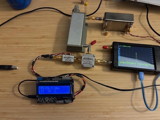
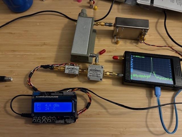
DIY RF Power Meter Achievement Unlocked (initial functionality achieved). Reviewed code, made tweaks, found cal-offset magic numbers and calibrated temperature (single point) and input RF level over -55 to +5 dBm at my test oscillator’s frequency of 100 MHz. RF Power Meter works stand-alone (no PC). Would like to add serial output data in future, but no rush at the moment. Thanks to DL9SEC for sharing his Arduino code for a similar RF sensor!
#HamRadio#TestEquipment#RFPower

Photo of the +5 dBm level test using same setup as -55 dBm, just different step attenuator setting. Sensor is within 1 dB of TinySA-Ultra reading over +5 to -55 dBm level (measured in 10 dB steps). Also calibrated temp reading using a separate 1-wire/Arduino sensor to be within 0.5 C at the set point temp.
Photo of -55 dBm calibration setup with 100 MHz oscillator, 5 dB pad, 0-70 dB 10 dB step attenuator, 2-way splitter, TinySA-Ultra level monitor, and Mini-Circuits ZX47-55 sensor connected to an Arduino with LCD display shield. Sensor is powered from a +12V wall wart power adapter. It works!
  • Copy link
  • Flag this post
  • Block
Log in

bonfire.cafe

A space for Bonfire maintainers and contributors to communicate

bonfire.cafe: About · Code of conduct · Privacy · Users · Instances
Bonfire social · 1.0.0-rc.2.21 no JS en
Automatic federation enabled
  • Explore
  • About
  • Members
  • Code of Conduct
Home
Login