

Today will be an electronics building day, assembling a prototype TPS62933P-based power supply board to get familiar with the chip before using them in upcoming designs.
0 Boosts
0 Likes
The starting point: a blank PCB. This time I got OSP finish so the pads look like bare copper.
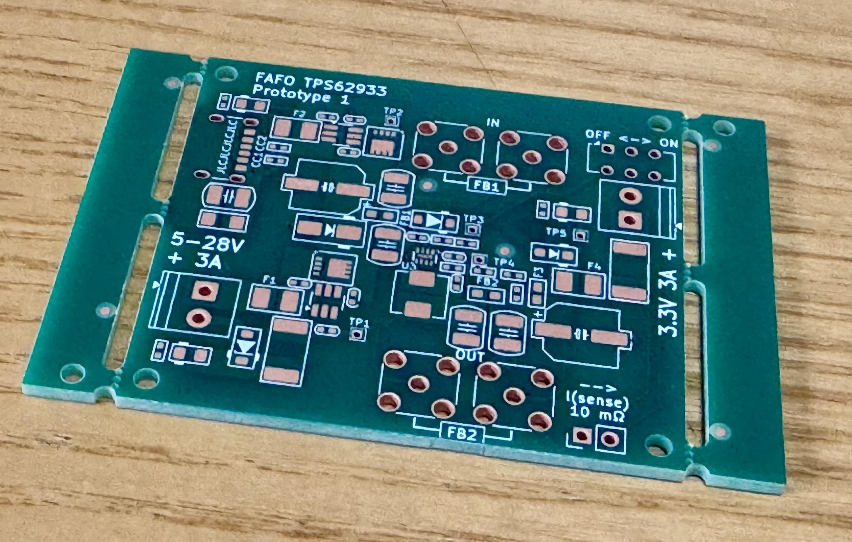


@jpm why did you go with OSP? I always end up using ENIG but OSP seems scary with the whole "don't bother trying to rework it more than once" issue. Is it not that bad?
@bipolaron it’s a $0 option with JLCPCB now, figured I’d give it a go and see how it works. Actually pretty happy with it, just needs plenty of flux during re-work

@jpm FAFO TPS62933P PROTOTYPE 1 - love it
Solder paste stencil. I don’t have a stencil jig, and I’ve always hated aligning stencils by hand, so this time I added two 2mm holes to both the PCB and stencil, and am using M2 screw sized pins for alignment.
2 media files
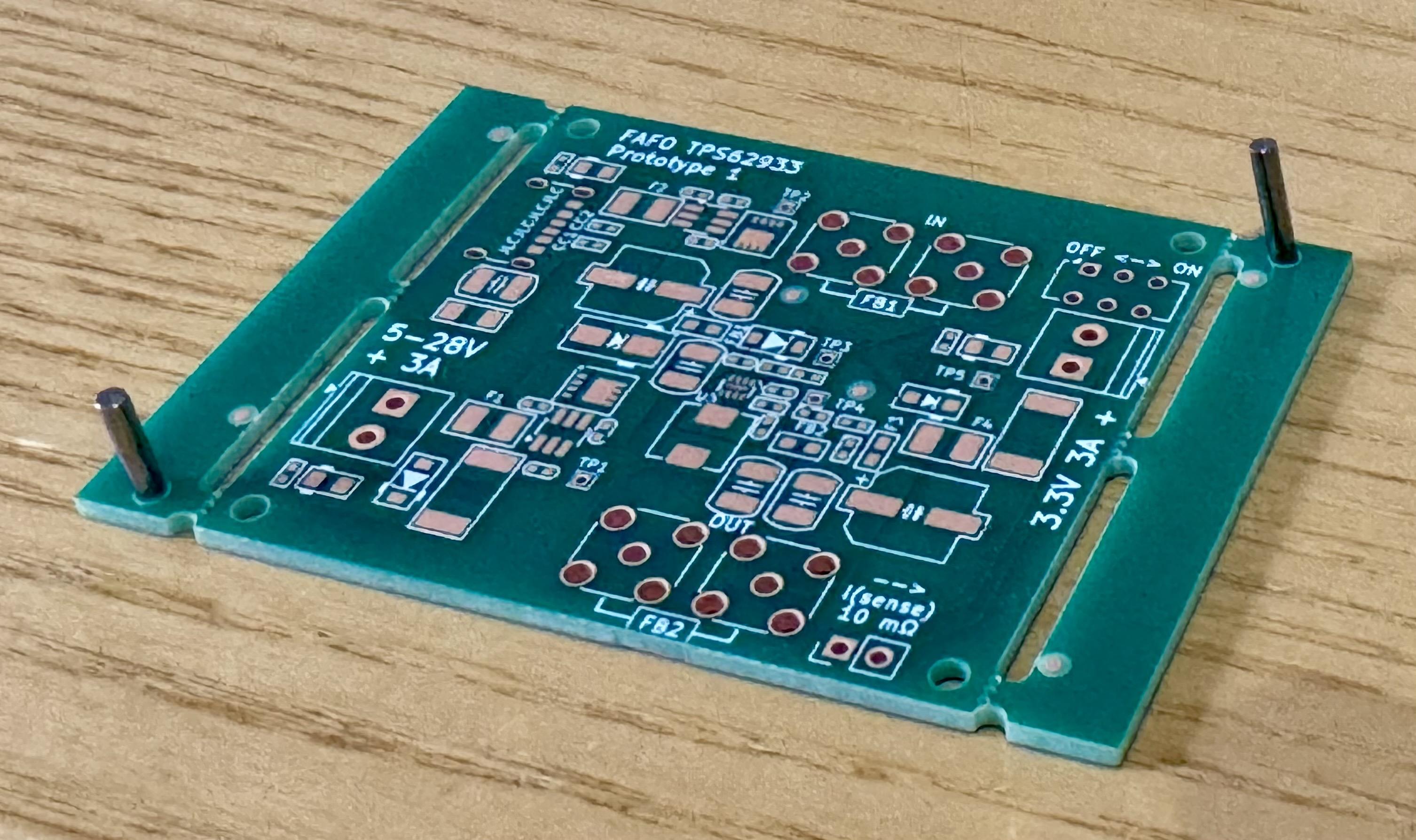
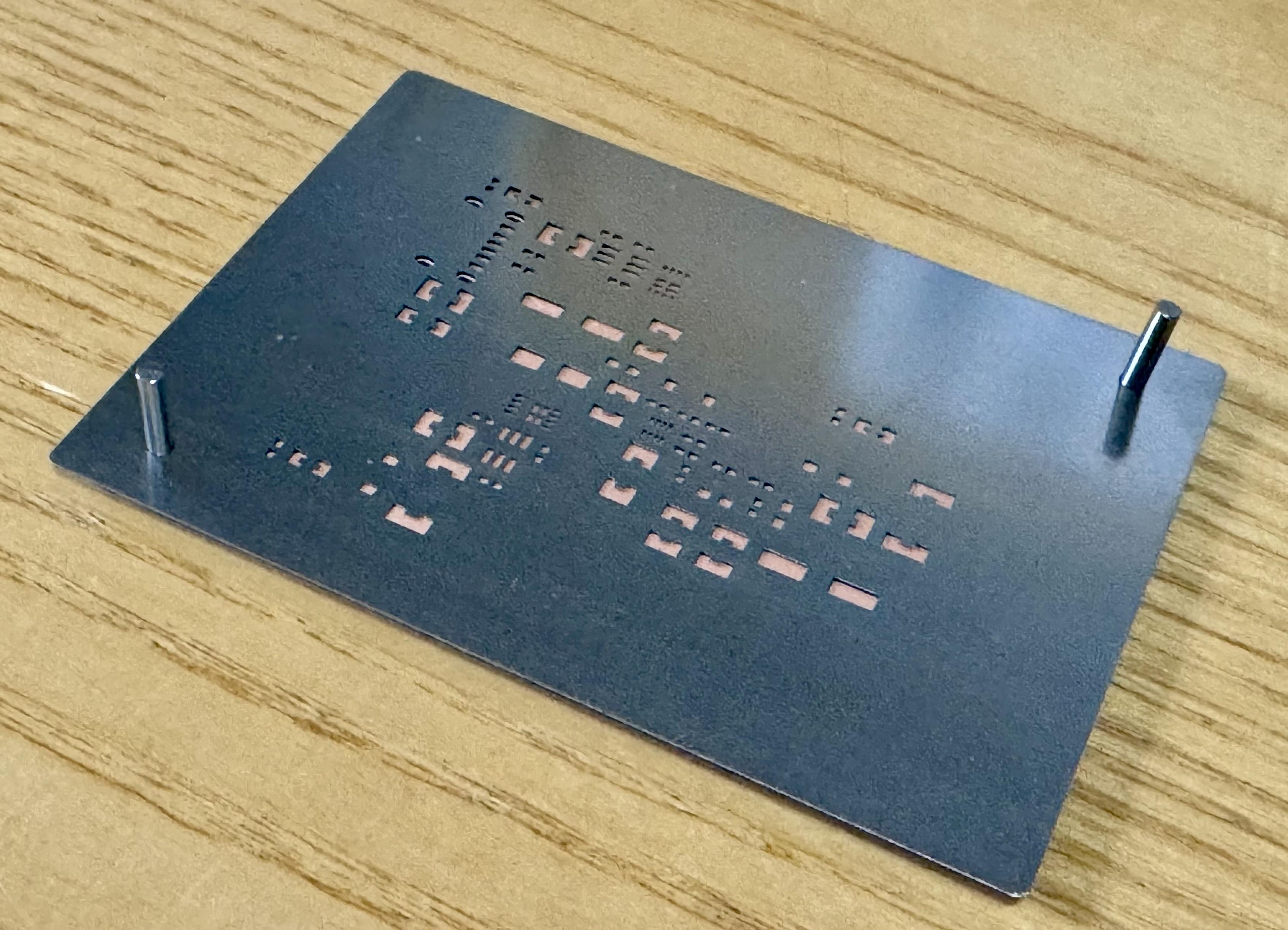




@petrillic @jpm @mos_8502 definitely stealing that alignment trick, are you then managing without even a frame? I can never get the floppy kind to work reliably.
and yeah, I have JLC give me rails on assembled boards always, but it is mixed on bare PCBs. maybe it's regional?


@petrillic @jpm What I usually do is use PCBs taped down as a sort of alignment jig, but this is way smarter.
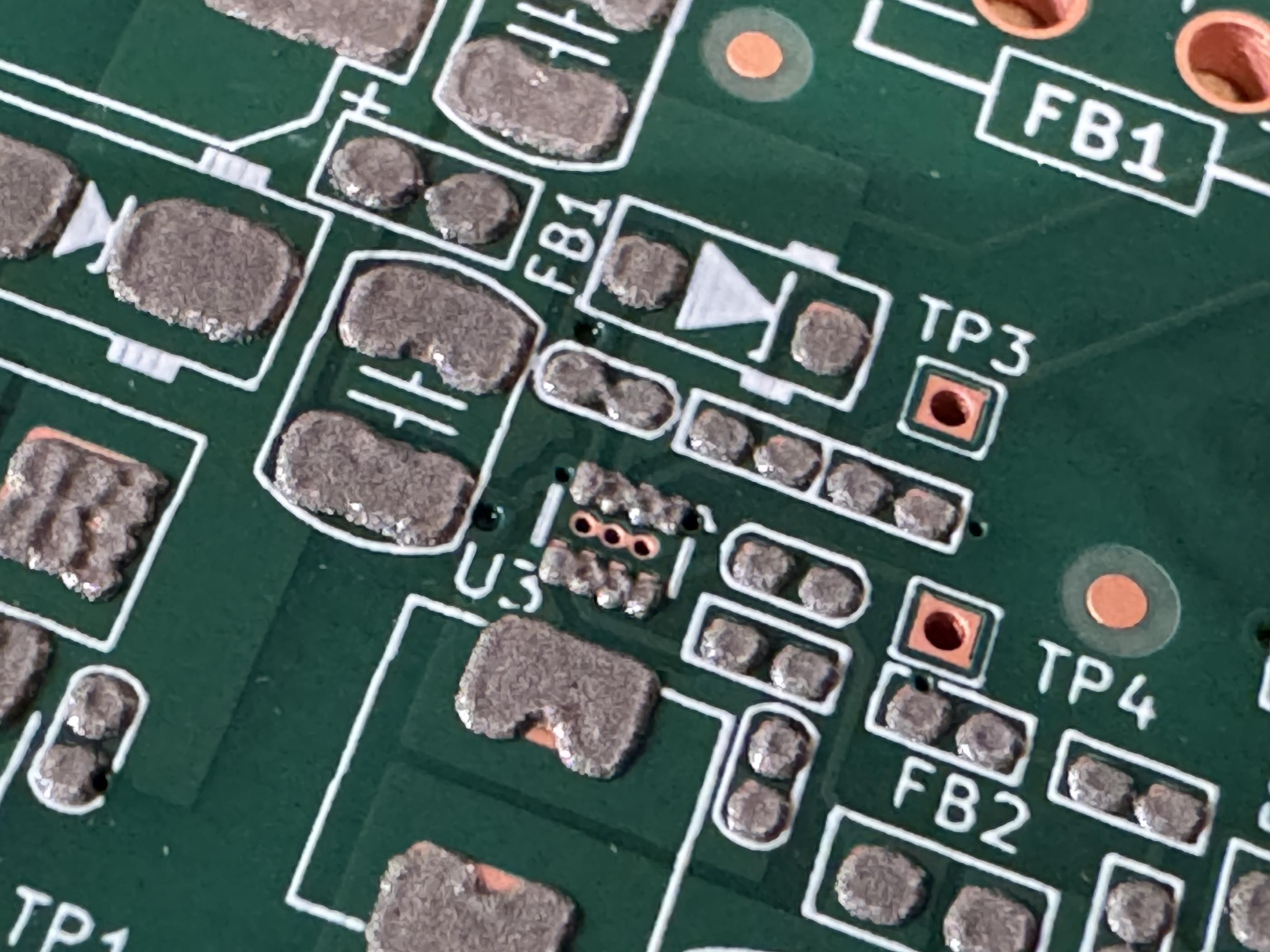
Yeah okay this works stupidly well. The smallest footprint on the board is this SOT-563, and I can’t see any green soldermask on the first position attempt
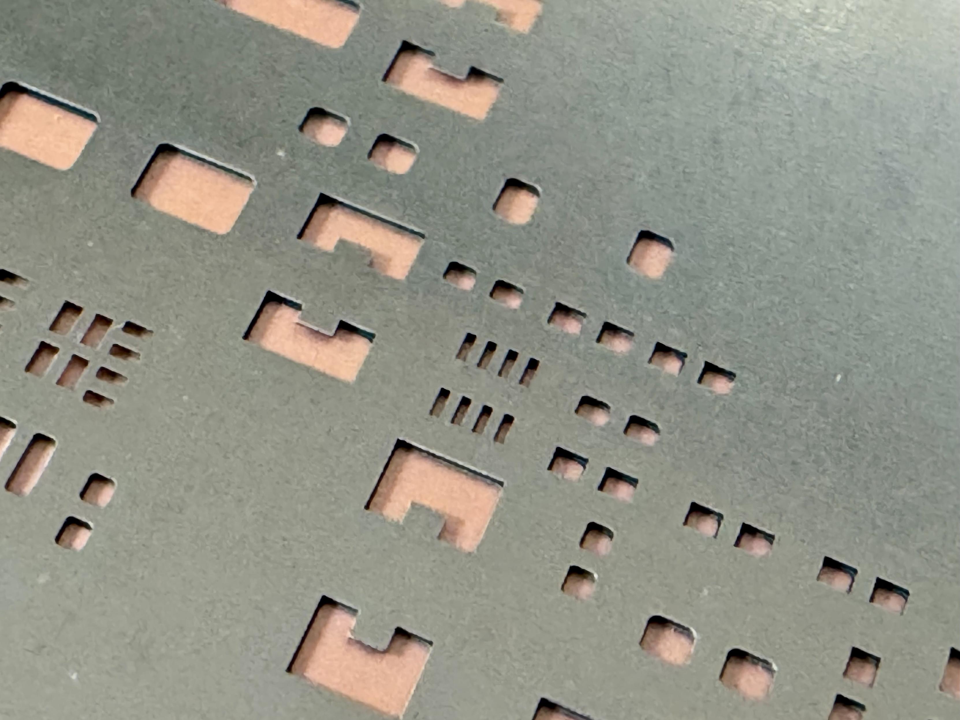
Oh dear, I think this paste has turned to shit. I’ll give it a go anyway because there seems to be the correct amount there
Hand-placing time! I need a PNP machine
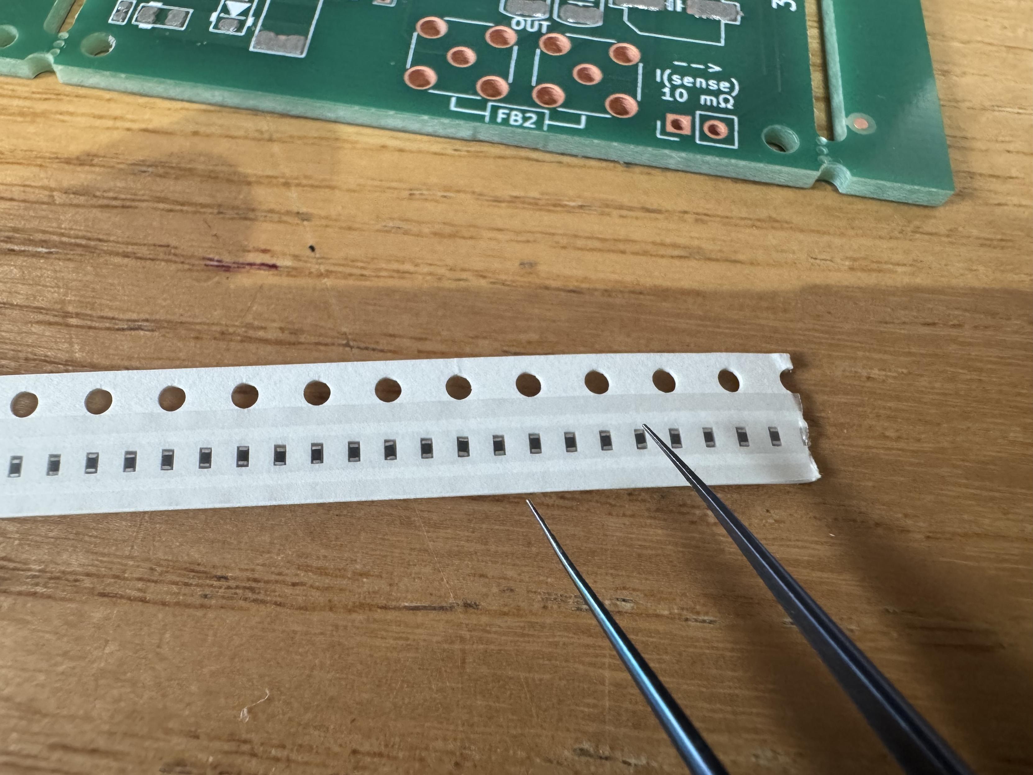
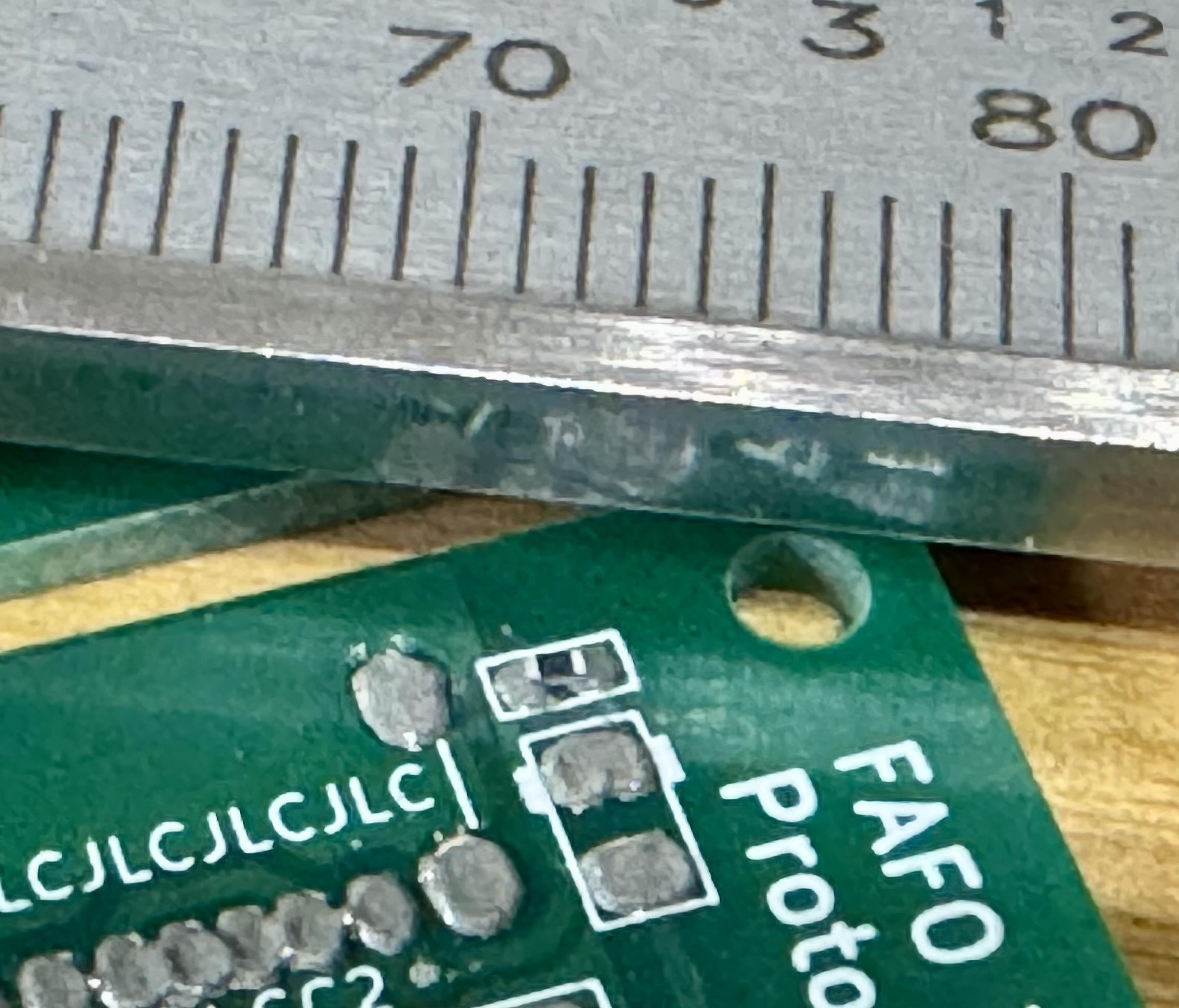
2 down, eleventy billion to go. 1mm division ruler for scale
Getting there…
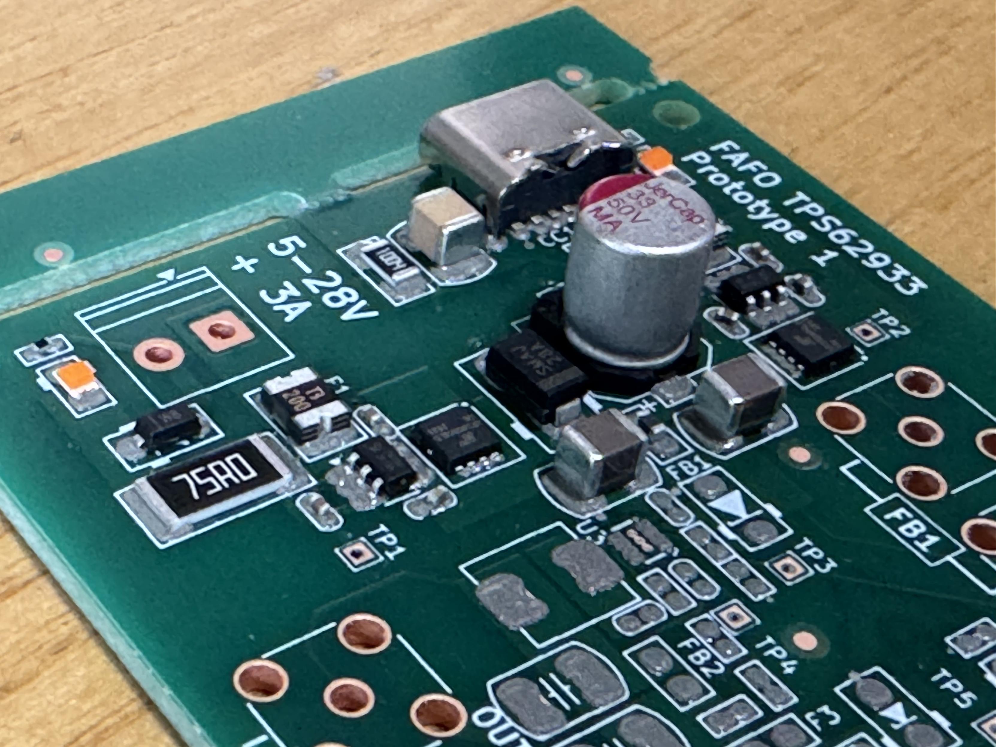
Ugh done. Now bake at 250°C for 30 seconds
Trust the surface tension. Trust the surface tension. Trust the surface tension. Trust the surface tension. Trust the surface tension. Trust t
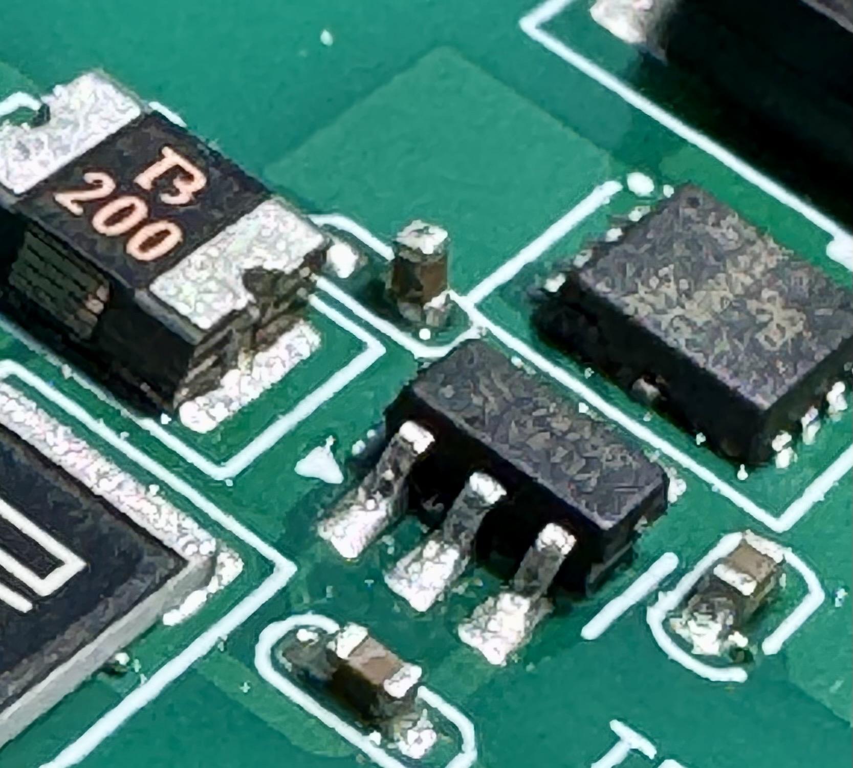
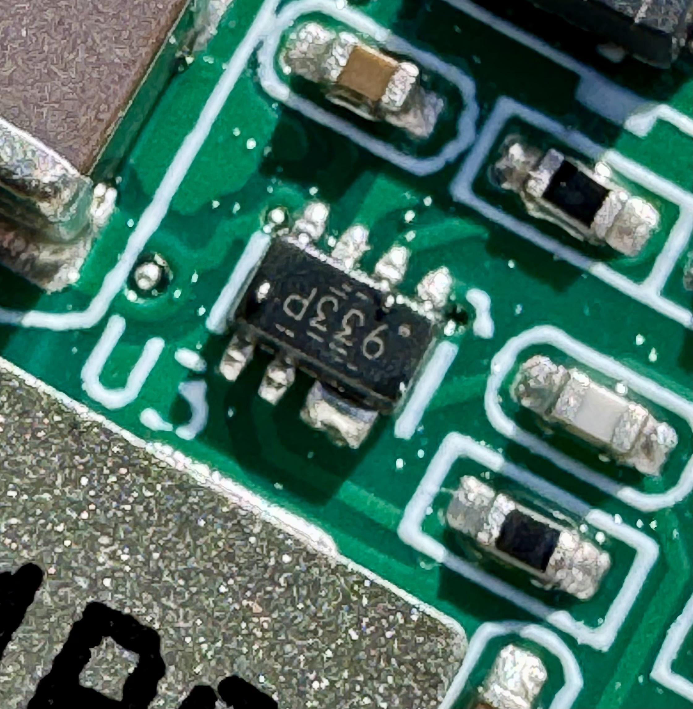
And possibly a movement, I’ll have to test this for continuity
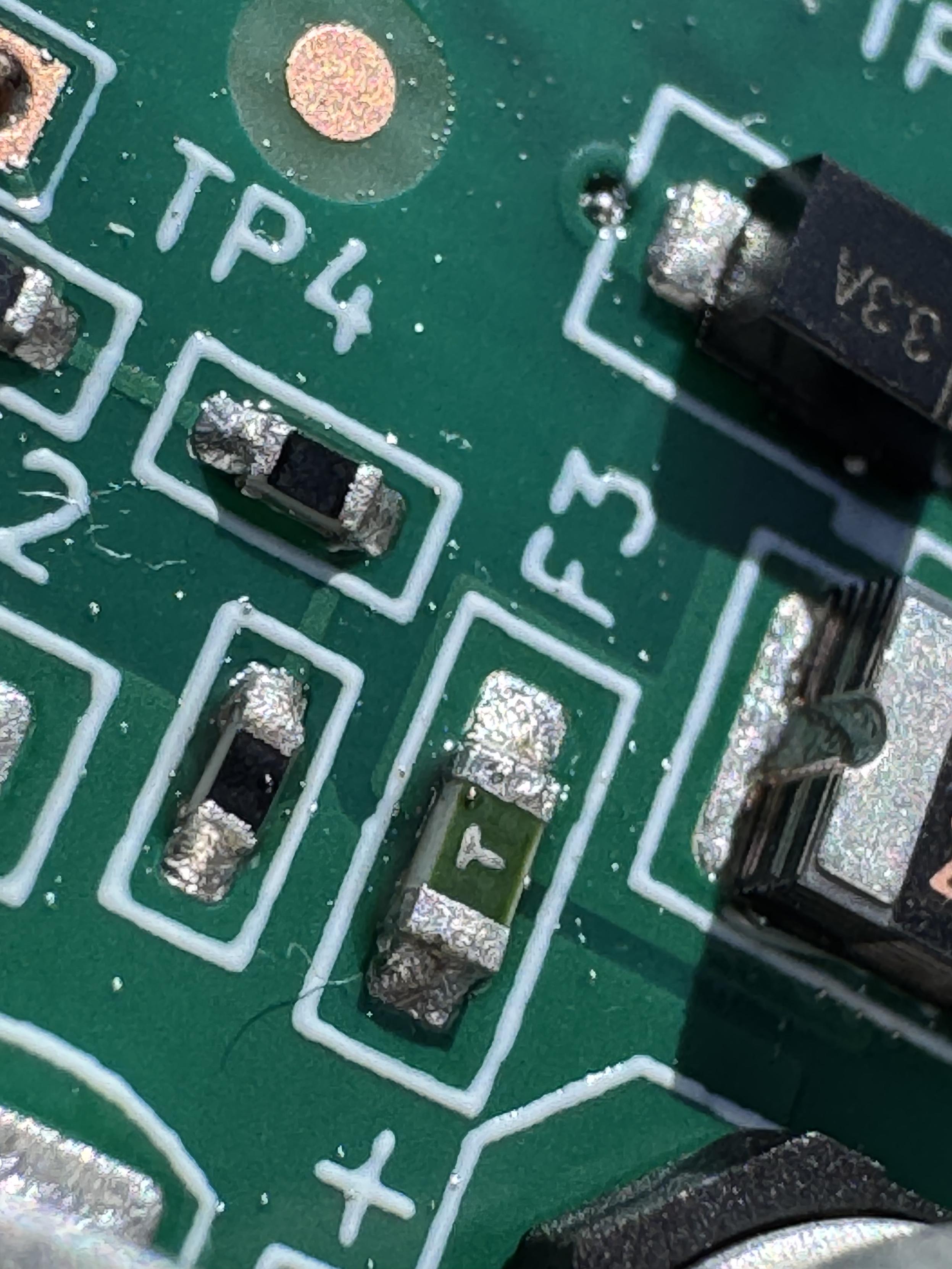
… duh of course this will show continuity, it’s a goddamn fuse
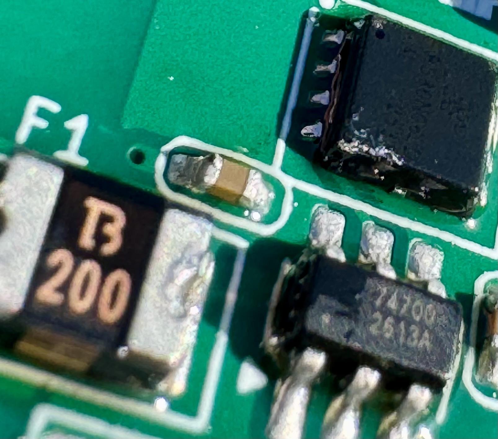
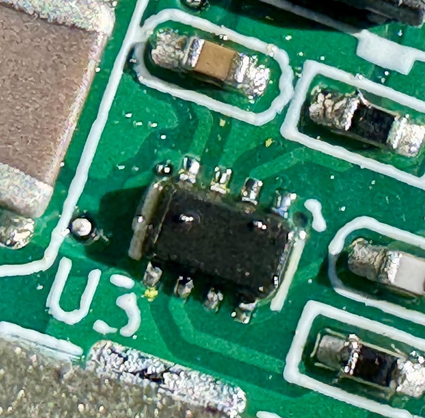
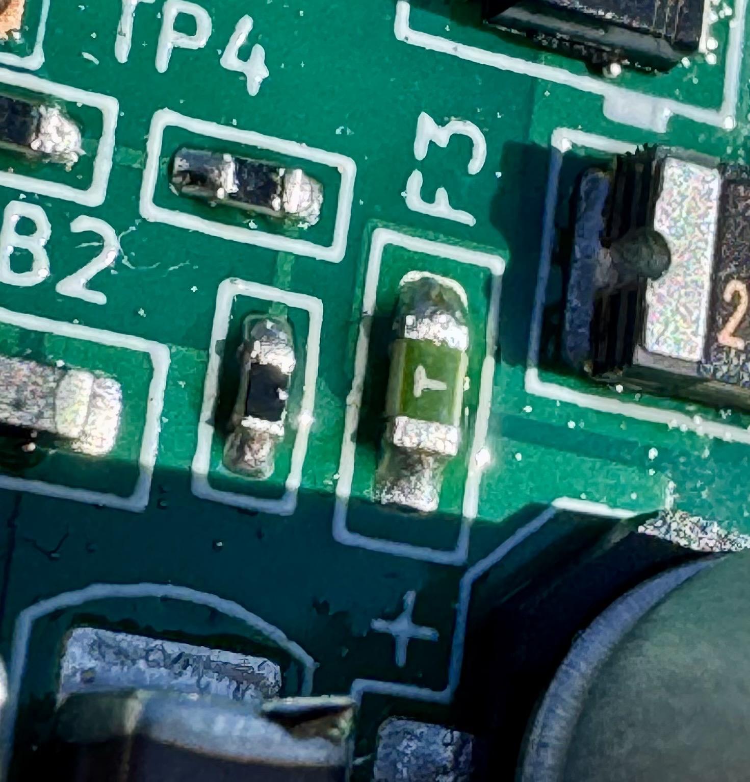
It is time, for re-work crime
No more tombstone
No more bridge
And fuse is nicely centered now
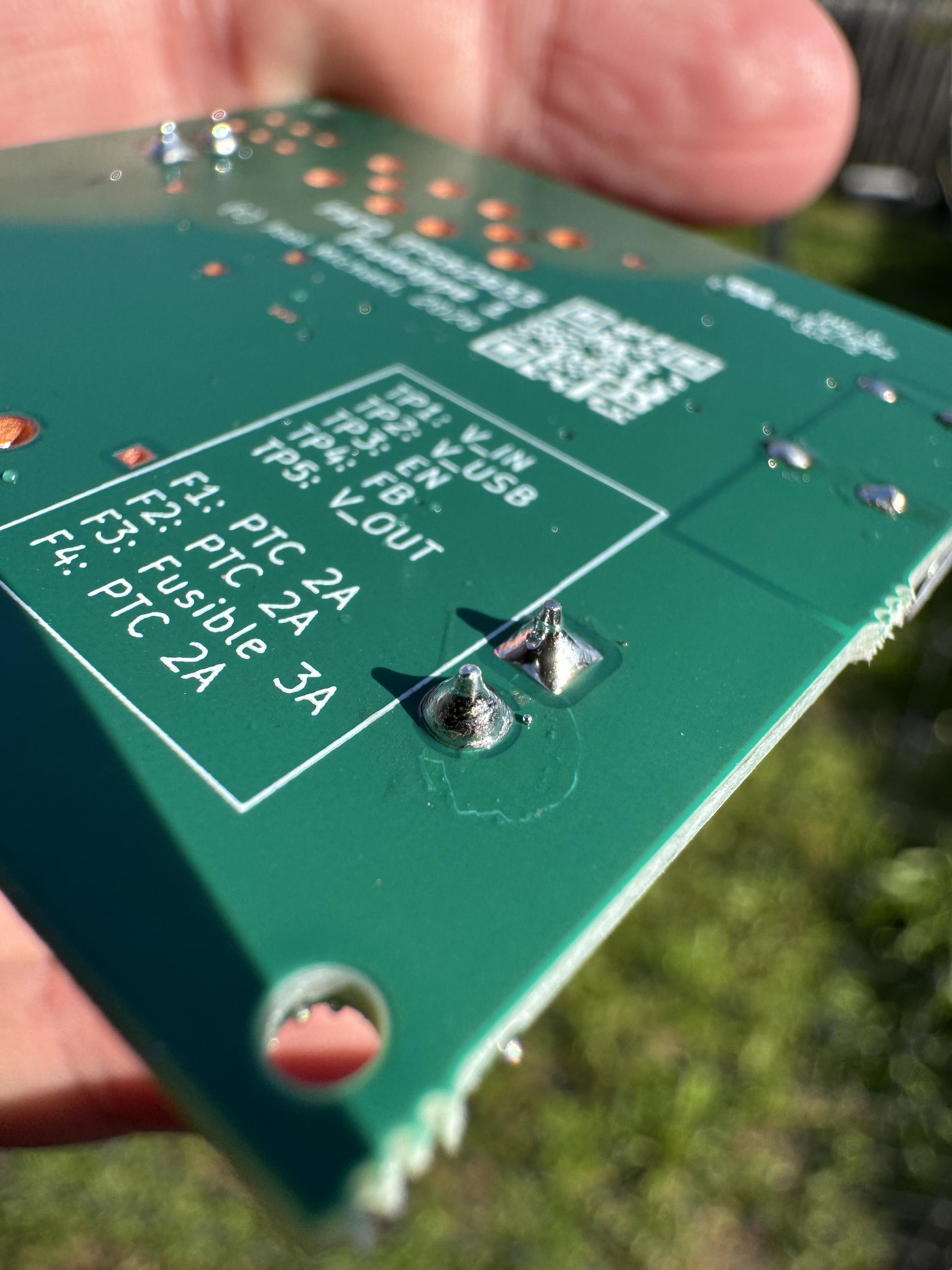
PTH hand-soldering done
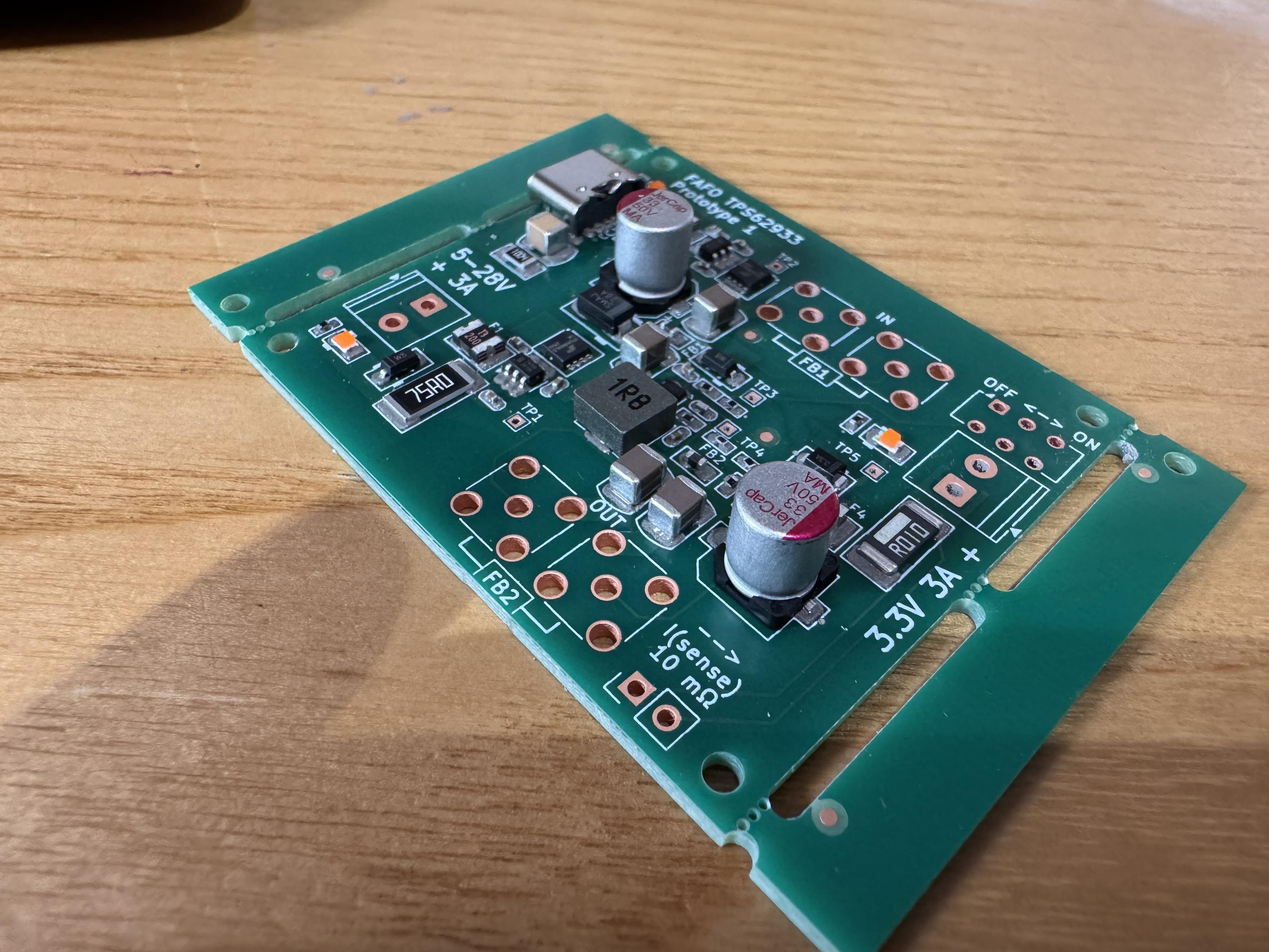
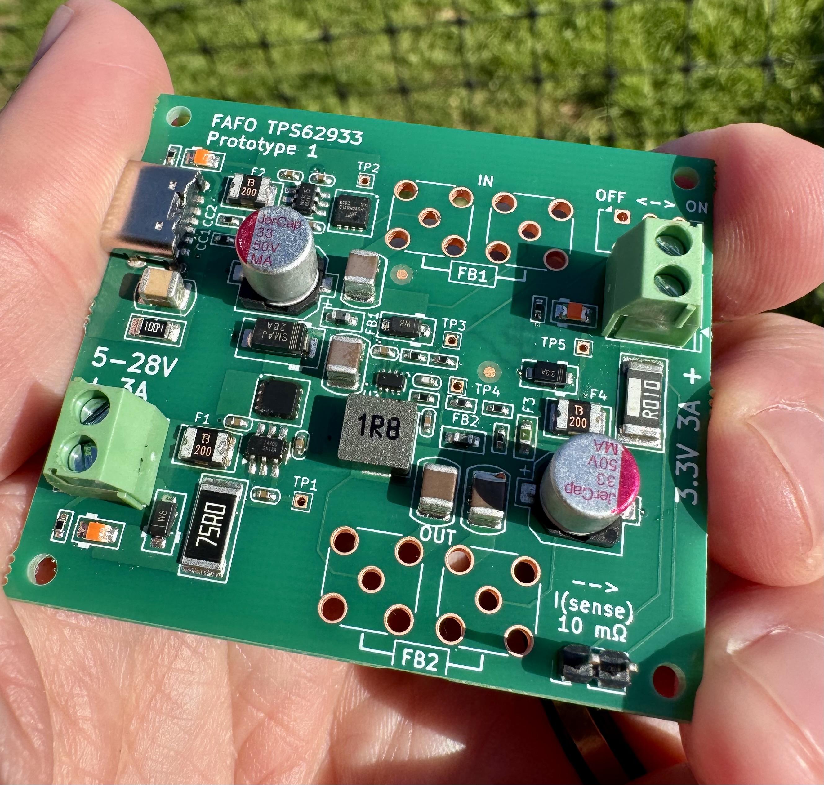
Looks like a real thing now!
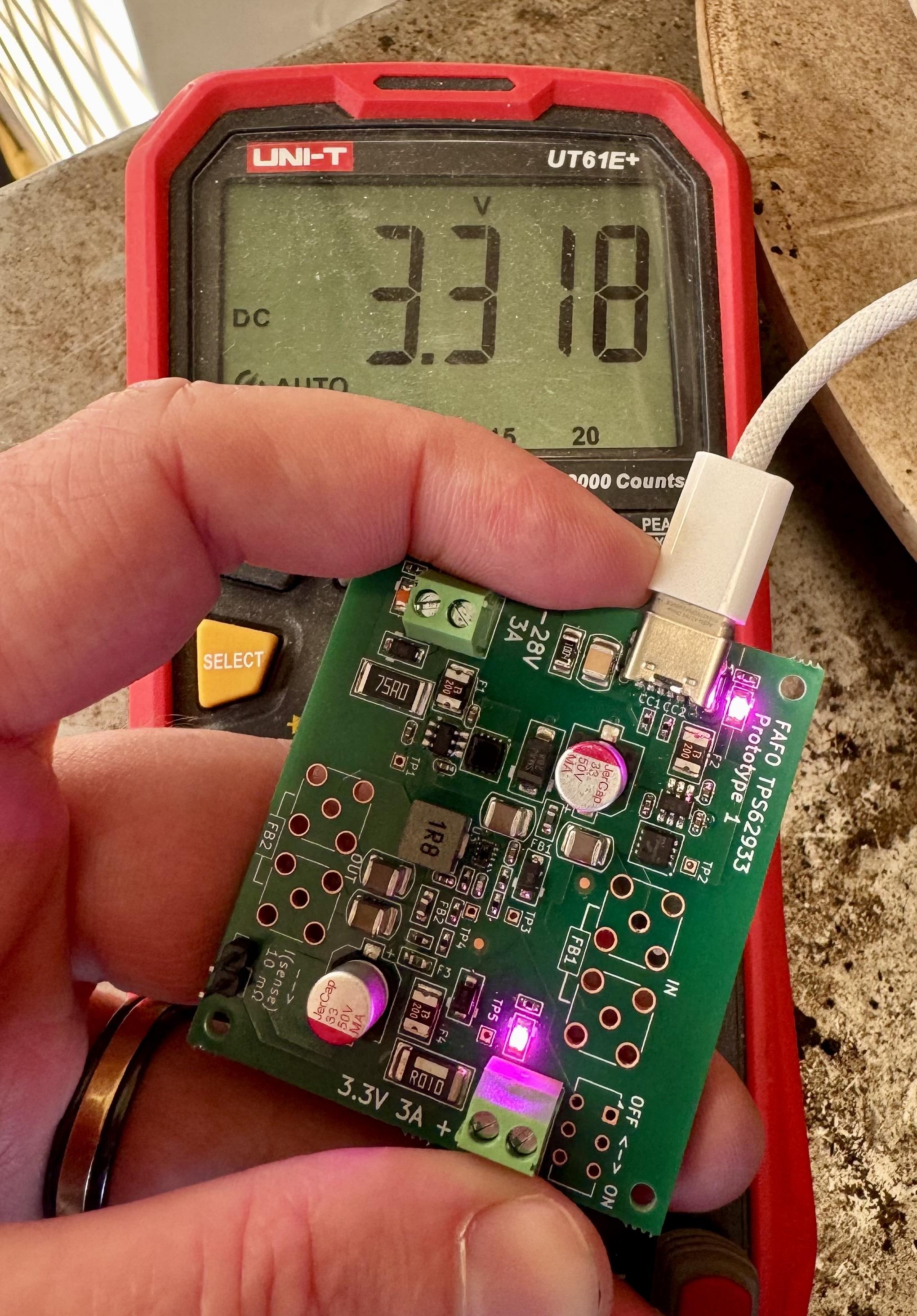
Oopsiedoodle, I bought and put wrong resistors for the “precision enable” voltage divider. Enable voltage is 4.9V. Which a USB port and shitty cable might not reach…
Only things left to do is test with 12-24V input, stick a big load across it, and measure output voltage ripple
Okay, 24V input “works” - except for the 5-24V DC input power LED circuit.
Whose stupid calculations came out to a 75ohm series resistor for the Zener circuit? Yeah of course the Zener diode is going to start smoking when it tries to dissipate 1.2W of heat.
On the other hand, 3.318V is only +0.5% from 3.30V, and is within the design goal of +/- 1.5% voltage regulation!
So, uh, it turns out my resistor divider calculation WAS correct, there was a different issue: the ideal diode controller on the USB input wasn’t working. There was a short between V(bus) and V(cap), which was causing the charge pump to not provide the voltage required to activate the MOSFET’s gate. The MOSFET’s body diode was providing the voltage instead, minus the diode V(f) of about 0.5V with no load. The resulting 4.5-and-a-bit volts was juuuuust enough to sometimes get the regulator to turn on with approximately no load, but as soon as a load appeared across the body diode the V(f) increased to easily hit under-voltage lockout.
Bit of flux and a hotplate reflow fixed that though.
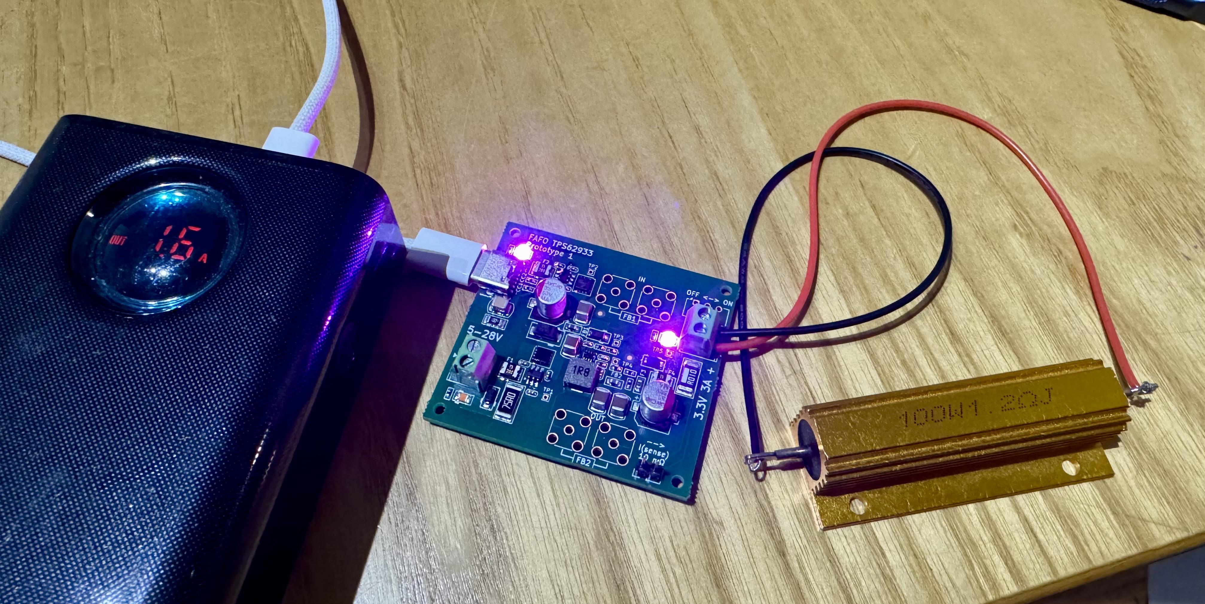

@jpm Instant fave for the stencil alignment pins and the silkscreen saying FAFO Prototype.