Michelson's 1881 interferometer. Although ultimately it proved incapable of distinguishing between differing theories of aether-dragging, its construction provided important lessons for the design of Michelson and Morley's 1887 instrument.
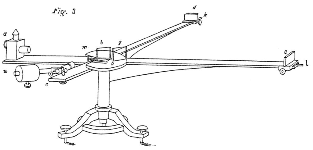
This is a technical line drawing labeled Fig. 3, illustrating the layout of Michelson’s original interferometer apparatus. The instrument rests on a central pedestal base with adjustable legs for leveling.
From the center extends two perpendicular arms of equal length, each supporting various optical components.
At the left end (marked a), a light source directs a beam toward a half-silvered mirror or beam splitter (labeled m) placed at the center.
The beam is divided into two paths—one traveling along the horizontal arm (b–c) and the other along the vertical arm (b–d).
Each arm contains mirrors and adjustable mounts (labeled l, k, etc.), which reflect the light back toward the center.
At the center, the returning beams interfere with each other, producing an interference pattern observable through an eyepiece or telescope (u).
The drawing shows precision details such as the rotatable table, the fine adjustment screws, and the mechanical supports, emphasizing the delicate alignment required for the experiment.
https://en.wikipedia.org/wiki/Michelson%E2%80%93Morley_experiment#/media/File:Michelson1881c.png