

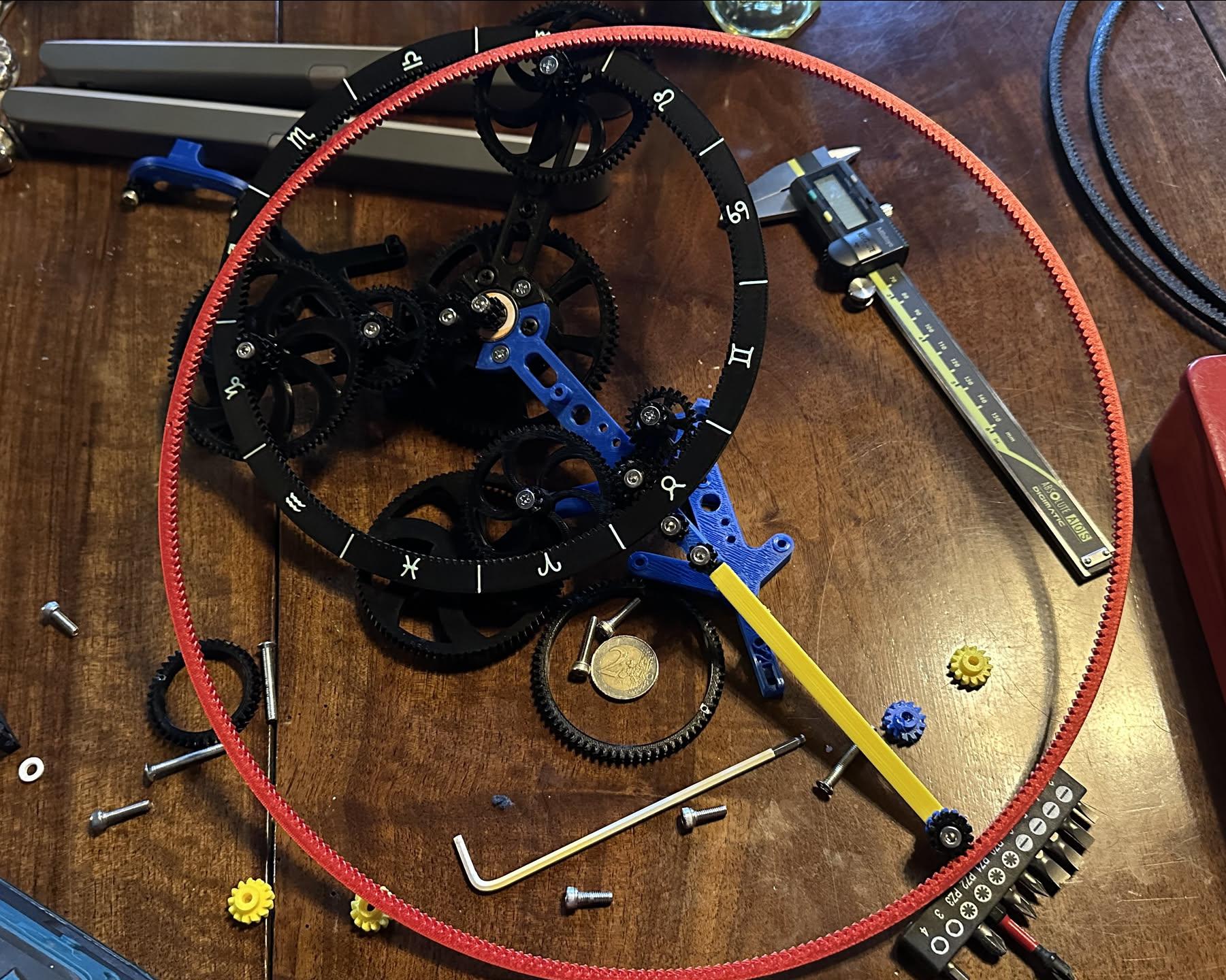
Forgot to include a work in progress photo of the giant Mars ring gear. It's really sqooshy (in the technical sense).
0 Boosts
0 Likes
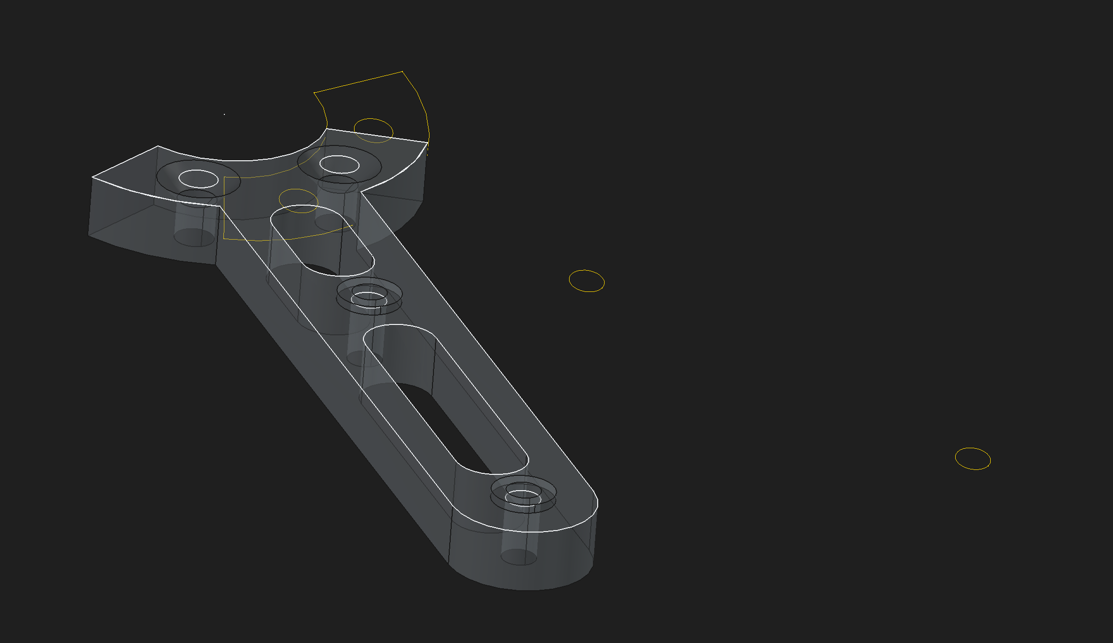
It seems that FreeCAD has somehow messed up the orientation of the binder copy (shown in yellow) of the base sketch that this part is derived from and this is leading to all sorts of constraint errors. But the original sketch (in white) still aligns with the derived sketch and the pad, so WTF happened to the binder? How can it's angle have been changed?
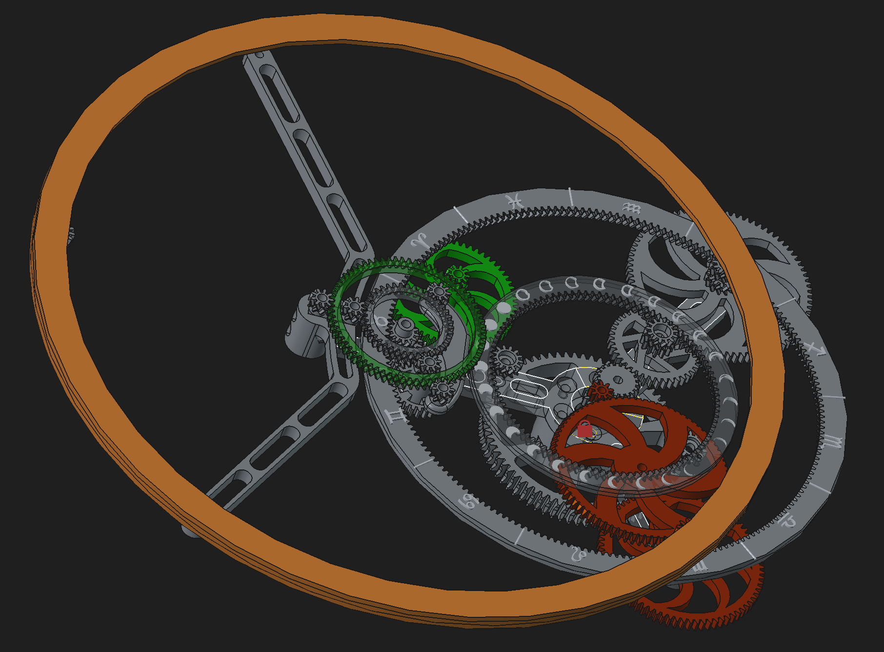
WTF double clicking on the binder in the tree view restored its orientation and most of the joints fixed themselves. Time to save, quit, and restart I think.
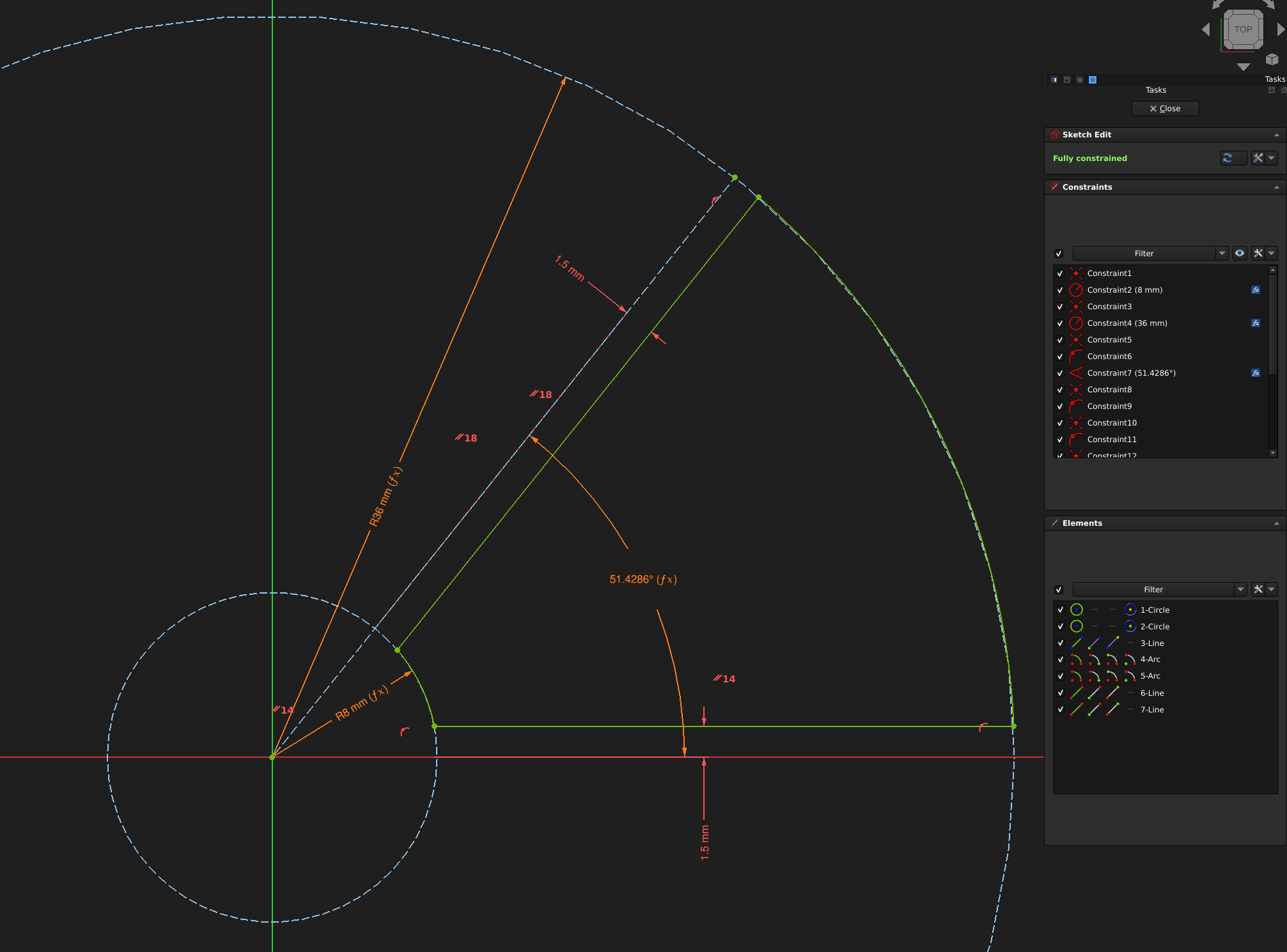
After way too much trial and error and segfaults in FreeCAD, I have a script that will generate parametric spokes and bevels for my gears. The wiki really needs some more complete examples of how to do things and there are so many ergonomic improvements that could be made in the Python interface.
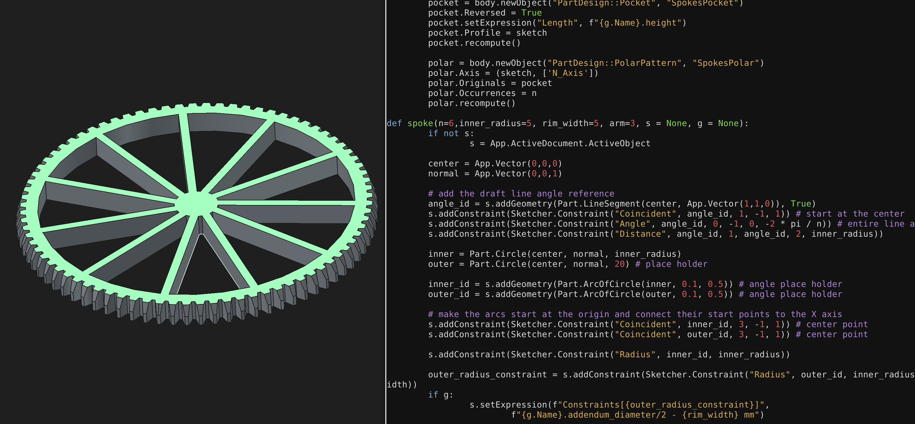
My Python library can make nicely constrained sketches now and I think it's much more usable than the direct port of the C++ API. I need to clean it up and post on the FreeCAD forums.

FreeCAD broke all of my assembly joints for some reason. Maybe it decided I wanted a tilt to the ecliptic plane. #glitch